Why Surge Protection is Needed in Solar PV System
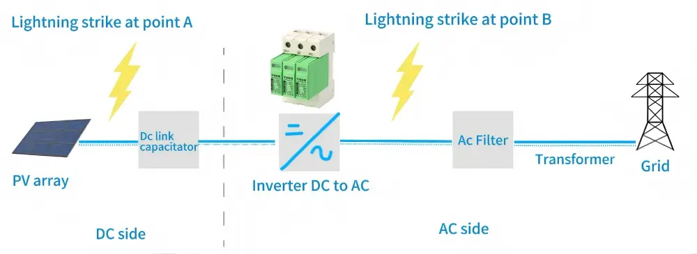
Solar PV systems operate in open environments where they are continuously subjected to varying weather conditions and grid fluctuations. Events such as lightning strikes, sudden grid switching operations, or rapid load changes can generate surge voltages that propagate through the system in a matter of milliseconds. These transient surges pose significant risks, including damage to sensitive inverter electronics and control boards, the occurrence of dangerous arc faults in PV modules and junction boxes, and unplanned system downtime that leads to costly repairs or replacements.
In a 2022 field report from Queensland, Australia, a rural farm’s 15 kW PV system failed after a summer thunderstorm. The cause? A high-energy voltage surge that bypassed the inverter’s limited internal protection. After the owner installed external Type 1+2 SPDs on the DC side and Type 2 SPDs on the AC side, the system ran through the next two storm seasons without a single surge-related shutdown.
Think of SPDs as pressure relief valves for electricity — they give excess voltage a safe escape route to the ground before it can break expensive components.
Surge Protection Device (SPD) Types and Selection Guide
SPDs are classified by how and where they protect the system. Choosing the right type depends on the surge source and your system layout.
| Type | Purpose | Typical Location | Example Use Case |
| Type 1 (T1) | Handles high-energy surges from direct lightning strikes or very close hits. | Service entrance or main distribution board. | PV systems in open, lightning-prone rural areas. |
| Type 2 (T2) | Protects against switching surges and indirect lightning. | Near inverters or in combiner boxes. | Rooftop PV in urban or suburban grids with frequent switching events. |
| Type (T1+T2) | Combines both functions for comprehensive coverage. | DC side near inverter or in combiner boxes. | Off-grid or hybrid systems in high-risk areas needing layered protection. |
Selection tips:
- Match Uc to your system voltage. Calibrate the SPD to a continuous voltage rating slightly surpassing the system’s highest steady-state voltage.For example, a 1000 V DC PV system would typically use a Uc of 1100 V.
- Check discharge capacity. Higher kA ratings provide more robust protection in high-risk zones.

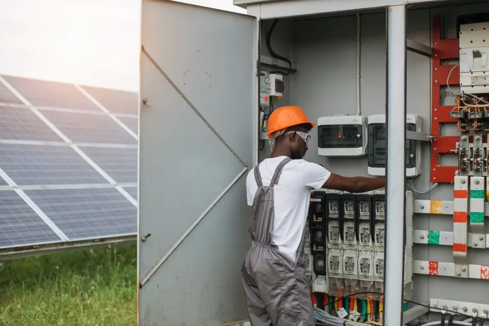
Key Installation Locations for SPDs in Solar Systems
Strategic SPD placement is essential. Installing just one SPD may protect a single point, but surges often enter from multiple directions.
- PV Array to Inverter (DC Side)
Place a DC SPD close to the inverter to protect it from surges traveling along PV cables. - Combiner Box or Near Inverter
Larger PV systems often combine multiple strings. Install SPDs in the combiner box to intercept surges before they reach the inverter. - Inverter Output (AC Side)
AC SPDs protect against surges coming back from the utility grid or from switching operations in generators. - Battery Storage Connection
In hybrid or off-grid systems, a DC SPD rated for the battery voltage protects expensive battery packs and their BMS from transient spikes.
Case study: A commercial warehouse in Stuttgart reduced inverter replacement incidents by 90% after installing both DC SPDs in the combiner box and AC SPDs in the main switchboard. Their maintenance team reported that “the cost of the SPDs was recovered in a single avoided inverter replacement.”
Step-by-Step SPD Installation Procedure
1. Choosing the Installation Location
- Locate SPDs within the shortest feasible distance from protected circuits.
- Minimize cable length to reduce surge path resistance.
2. Wiring Specifications and Best Practices
- Use cables rated for both system voltage and surge discharge current (often minimum 10 AWG for PV SPDs).
- Mark all DC polarity (+/–) and ground (GND) clearly.
- Route SPD wiring separately from signal cables to avoid induced voltages.
3. Grounding Requirements
- Aim for a grounding resistance ≤ 10 Ω (check with a ground tester).
- Keep grounding conductors short, straight, and direct to the main earth bar.
- Bond all system metallic parts to avoid potential differences.
4. Post-Installation Testing
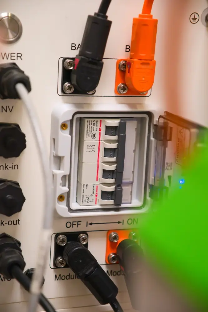
- A multimeter can be used to verify voltage, polarity, and continuity.
- Check SPD status indicators — green means operational, red or unlit means replacement is needed.
- For critical installations, perform an insulation resistance test and document the results.
Practical example: For a 5 kW residential PV system, installing a Type 1+2 DC SPD in the combiner box and a Type 2 AC SPD in the main distribution panel is typically enough to protect both sides of the inverter.
SPD Maintenance and Inspection
Regular Physical Checks
- Inspect SPDs every 6–12 months.
- Look for discoloration, burnt marks, cracks, or loose wires.
Monitoring Indicators and Replacements
- Use the built-in indicator window or LED.
- If it shows red, clear, or off — replace the module immediately.
Environmental Protection Measures
- Install SPDs in IP65-rated enclosures if mounted outdoors.
- Avoid locations with excessive vibration, dust, or corrosive gases.
Best Practices
- Layer your protection. Combine Type 1, Type 2, and Type 1+2 SPDs in critical points.
- Place SPDs strategically. Near inverters, combiner boxes, battery packs, and grid connections.
- Make grounding a priority. A poor ground connection can make the most expensive SPD useless.
- Replace when necessary. SPDs sacrifice themselves to protect your system — don’t run without a working unit.
Surge protection is not a luxury.This low-cost safeguard can prevent expensive equipment failures and prolonged power outages.