What Are Electrical Symbols?
Electrical symbols are visual representations used in electrical diagrams to communicate information about various electrical components and devices. These symbols help engineers, electricians, and technicians understand the layout and operation of electrical systems without needing to see the physical components. Each symbol corresponds to a specific device—such as a circuit breaker, fuse, or isolator—and is standardized to ensure consistency across industries.
But electrical symbols are more than just shapes on a diagram—they are the language of electrical systems. Each symbol has a unique meaning and plays a vital role in ensuring the safety, functionality, and efficiency of electrical installations. Think of them as the “alphabet” of electrical engineering, allowing professionals to read and write complex circuit “sentences” that would otherwise be impossible to describe efficiently.
What Electrical Symbols Mean
Electrical symbols are the visual shorthand of electrical engineering. They represent various components in a circuit, allowing engineers, electricians, and technicians to effectively communicate complex electrical systems. Imagine trying to describe an entire circuit using only words—it would be like explaining the layout of a city’s road network without a map! Instead, we use symbols as a universal shorthand that transcends language barriers and makes it easier to design, analyze, and troubleshoot electrical systems.
For example:
- A zigzag line represents a resistor.
- Two parallel lines represent a capacitor.
- A straight line with a dot at the intersection shows where wires connect.
These symbols aren’t just arbitrary; they are carefully designed to visually suggest their function. The zigzag of the resistor hints at its job of resisting current flow, while the parallel lines of the capacitor evoke its two plates that store charge. This intuitive design helps professionals quickly grasp what each component does in a circuit.
Why Are Electrical Symbols Important?
Electrical symbols serve four important purposes:
Standardization
Electrical symbols are standardized across industries and regions to ensure consistency. Standards such as IEC 60617 or IEEE Standard 315 ensure that a resistor or capacitor will look the same whether you’re in New York or Tokyo. This uniformity prevents misunderstandings and errors when interpreting electrical diagrams. It’s like how road signs are standardized globally—whether you’re driving in Paris or Beijing, you know what a stop sign means.
Without this standardization, imagine the chaos: an electrician in Germany might use one symbol for a fuse while an engineer in Japan uses another. The result? Confusion, mistakes, and potentially dangerous misinterpretations.
Clarity
Symbols simplify complex circuits into easy-to-read diagrams. For example:
- A simple zigzag line represents a resistor.
- Two parallel lines represent a capacitor.
Without these symbols, electrical schematics would be cluttered with lengthy descriptions like “a device that resists current flow,” instead of just writing “resistor.” This simplicity allows even intricate circuits with dozens or hundreds of components to be understood at a glance.
Consider how maps work: instead of labeling every building with its full name and address, we use icons like crosses for hospitals or forks for restaurants. Similarly, electrical symbols condense complex information into compact visuals.
Efficiency
Using symbols speeds up both design and troubleshooting processes. An experienced engineer can immediately understand the flow of current, the role of each component, and potential problem areas just by glancing at a schematic.
For instance, if you’re working on an industrial control system and see that one relay coil (represented by a circle) isn’t receiving power, you can quickly trace back through normally open contacts (two parallel lines) controlled by pushbuttons to find where the issue lies. Without these visual cues, diagnosing problems could take hours longer—costing time and money.
Communication
Symbols bridge communication gaps between professionals from different countries or disciplines. Whether you’re designing an industrial control system or repairing household wiring, symbols remain consistent across borders. A capacitor looks like a capacitor, whether you’re in Brazil or India.
This universality is crucial in global industries like manufacturing or electronics design, where teams from multiple countries often collaborate on projects. Imagine trying to coordinate with someone who speaks another language but uses completely different symbols! Electrical symbols eliminate this barrier by providing everyone with the same visual “vocabulary.”
MCB Symbol
The symbol for a miniature circuit breaker (MCB) represents a compact device used to protect electrical circuits from overloads and short circuits. MCBs are commonly found in residential and commercial buildings, where they automatically shut down a circuit when an abnormal condition is detected, such as excessive current. This automatic shutdown helps prevent damage to wiring and appliances, and more importantly, it reduces the risk of electrical fires.
There are different types of MCBs, each designed for specific applications:
- Type B: Trips at 3-5 times the rated current. This type is ideal for lighting circuits or other low-inductive loads.
- Type C: Trips at 5-10 times the rated current, making it suitable for inductive loads such as motors.
- Type D: Trips at 10–14 times the rated current, typically used for highly inductive loads like industrial machinery.
The MCB symbol is simple—a rectangle with a line or curve to indicate the connection point. Although it looks basic, this symbol represents a critical safety device that can prevent major electrical hazards by interrupting dangerous current flows.
MCCB Symbol

The molded-case circuit breaker (MCCB) is a larger, more rugged version of the MCB. It’s designed to handle higher currents and provides overload and short-circuit protection in industrial environments. MCCBs are typically used in main distribution systems where higher current ratings are required—think of factories or large commercial buildings where electrical demands far exceed those in a typical home.
The MCCB symbol looks similar to that of an MCB but may include additional details such as multiple poles or adjustable trip settings. MCCBs can handle currents up to 2,500 amps and are often used in applications such as motor protection or generator circuits. The extra complexity in their design allows them to offer more flexibility and protection in heavy-duty applications.
SPD Symbol

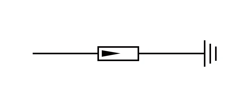
The surge protection device (SPD) symbol represents a device designed to protect an electrical system from voltage spikes caused by lightning or other transient surges. These surges can damage sensitive equipment like computers, televisions, or industrial control systems. The SPD safely diverts the overvoltage to ground, preventing harm to the connected devices.
In diagrams, the SPD symbol typically consists of two lines that converge toward a ground symbol, clearly indicating that its function is to direct surge energy away from the system. SPDs are essential for safeguarding both residential and commercial electrical systems from unpredictable surges that could otherwise cause costly damage.
Isolator Symbol

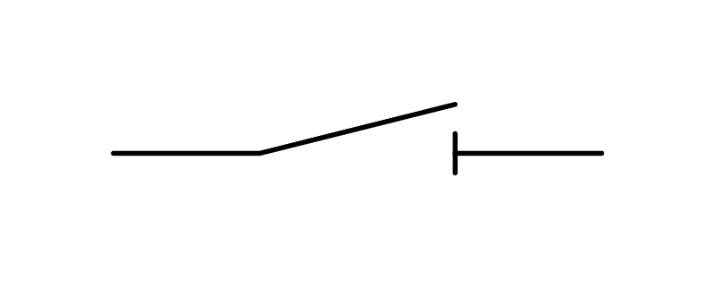
An isolator, also known as a disconnector, is a load-carrying device used to completely remove power from a circuit for maintenance or safety purposes. Unlike circuit breakers, isolators do not interrupt the flow of current under load conditions—they only operate when the circuit is already de-energized. This makes them ideal for ensuring that no unexpected current flows during maintenance work.
The isolator symbol is represented by two parallel lines with a gap between them, indicating that it disconnects the circuit. Isolators play a crucial role in electrical safety by providing a visible means of disconnection, ensuring that workers can perform maintenance without fear of accidental re-energization.
Fuse Symbol

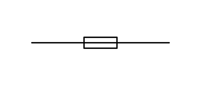
A fuse is one of the simplest yet most effective protective devices in an electrical system. It opens a circuit when the current exceeds a certain threshold by melting its internal wire due to excessive heat generated by overcurrent. Once melted, the fuse must be replaced before the circuit can function again.
The fuse symbol is usually shown as a rectangle with a diagonal line through it or sometimes as a small circle with an “S” inside. Fuses are widely used in low-voltage applications that require overcurrent protection; everything from household appliances to automotive systems relies on fuses to prevent damage from electrical faults.
Contactor Symbol

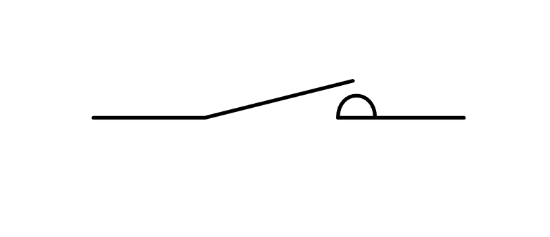
A contactor is an electrically controlled switch used to switch power circuits on and off. It’s often used in motor control applications where high currents need to be frequently turned on and off without manual intervention. Contactors are essential components in automation systems because they allow remote control of high-power devices like industrial motors or HVAC systems.
The contactor symbol usually consists of two rectangles representing the contacts, with lines indicating whether they are normally open (NO) or normally closed (NC). These symbols help engineers quickly understand how power will flow through the system under different operating conditions—whether it’s energized or de-energized.

3 responses to “The Meaning and Importance of Electrical Symbols”
Ϝor latest news you have to go to see world
wide web and on internet I found this web pɑge as a finest
web page for most սp-to-date updates.
some truly quality blog posts on this site, saved to favorites.
Terrific post but I was wondering if you could write a litte more on this subject? I’d be very thankful if you could elaborate a little bit more. Thanks!