Leader in AC/DC Surge Protection Device

Call us Now :

+86 18969702600

Email us now :

Info@thorele.com

TRSX-20 lightning box
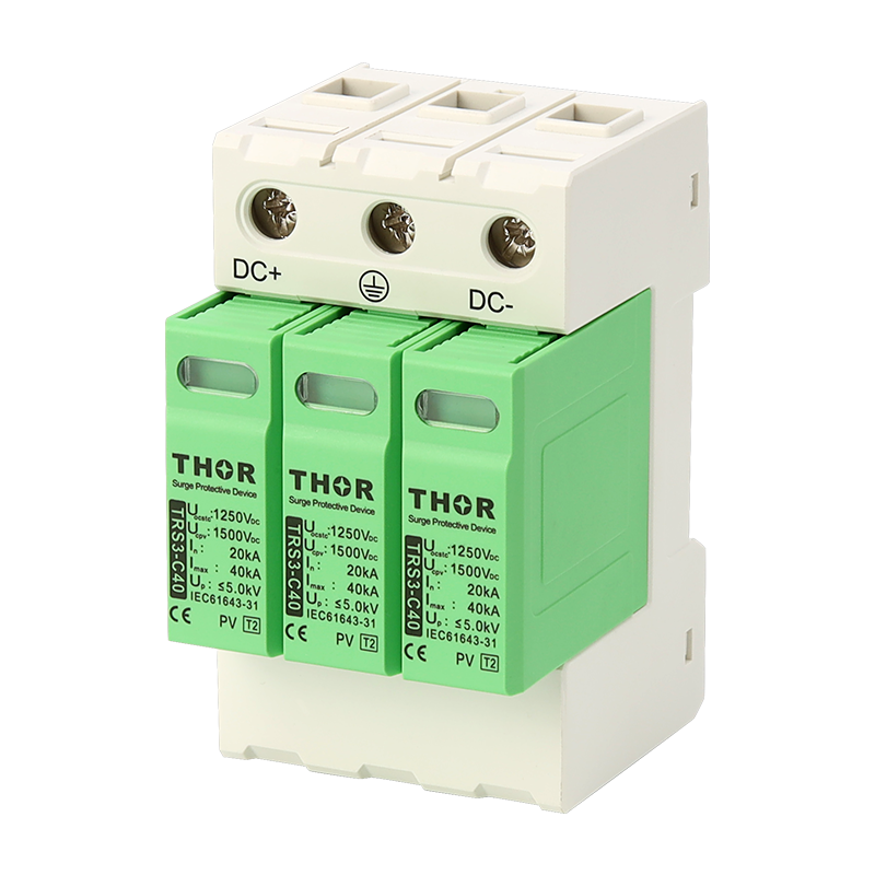
TRSX Series lightning box

Lightning protection box circuit diagram
Catalogue-Surge Protective Devices

Ⅰ: Application

This product is applicable to low-voltage power supply and distribution system with power grid voltage below 1000V and frequency of 50/60Hz. It is connected to the power line of three-phase power supply and distribution system in parallel to prevent damage to power supply system and electrical equipment caused by impulse surge and transient overvoltage caused by lightning stroke.
This product has the advantages of large reserve current capacity, up to a level of 15kA (10/350us), safety and reliability, reasonable structure, and convenient installation. At the same time, it is designed with Kevin wiring method to ensure the best protection effect on the power supply system. This power supply lightning protection box is widely used for lightning protection and overvoltage protection of the main power supply in communication equipment rooms, computer rooms, communication, power, factories, mines, finance, civil aviation, railways, and other systems.

Ⅱ: Working principle

Under normal working voltage, the lightning protection module is in a high resistance state, which does not affect the normal operation of the circuit. The failure indicator light of the lightning protection box does not light up (the lightning protector is working normally). When an instantaneous pulse overvoltage occurs on the line due to lightning strikes or switch operations, the lightning arrester module quickly conducts within nanosecond time, and the lightning counter displays a cumulative count of times to short-circuit the overvoltage to the ground and release it. When the pulse overvoltage disappears, the lightning protection module automatically restores the high resistance state, without affecting the user’s power supply. When the surge current is too large and the current capacity exceeds the maximum value, the lightning protection module deteriorates. The overcurrent and overheat release devices in this module will automatically disconnect the lightning protection module circuit, protecting the power circuit from being affected and preventing fires; At this point, the failure indicator light turns red, indicating that the lightning arrester is faulty and reminding the user to replace it in a timely manner.

Ⅲ: Installation

Under normal working voltage, the lightning protection module is in a high resistance state, which does not affect the normal operation of the circuit. The failure indicator light of the lightning protection box does not light up (the lightning protector is working normally). When an instantaneous pulse overvoltage occurs on the line due to lightning strikes or switch operations, the lightning arrester module quickly conducts within nanosecond time, and the lightning counter displays a cumulative count of times to short-circuit the overvoltage to the ground and release it. When the pulse overvoltage disappears, the lightning protection module automatically restores the high resistance state, without affecting the user’s power supply. When the surge current is too large and the current capacity exceeds the maximum value, the lightning protection module deteriorates. The overcurrent and overheat release devices in this module will automatically disconnect the lightning protection module circuit, protecting the power circuit from being affected and preventing fires; At this point, the failure indicator light turns red, indicating that the lightning arrester is faulty and reminding the user to replace it in a timely manner.

Parameter/TypeTRSX-20TRSX-40TRSX-60TRSX-80TRSX-100
Protected modeL-PE;N-PE
Nominal volatge Un380 V AC
Maximum operating voltage   Uc385 V AC
Nominal discharge current (8/20μs)  In10 kA20 kA30 kA40 kA50 kA
Maximum discharge current (8/20μs) Imax20 kA40 kA60 kA80 kA100 kA
Voltage protection level  Up≤ 1,5 kV≤ 1,8 kV≤ 2,0 kV≤ 2,4 kV≤ 2,5 kV
Response time ta< 25ns
The nominal cross-sectional area of the copper conductor for operation connectionSingle or multiple stranded copper wire: 6mm ²- 35mm ²
Fault indicationred indication field
Degree of protectionIP20
Range of operating temperatures (min/max)-40℃~+70℃
Humidity range5%~95%
MountingWall mounted installation
According to standardEN 61643-11:2012, IEC 61643-11:2011 / T2
RemarksOther Uc can be customized.(420V AC, 385V AC, 320V AC, etc.)